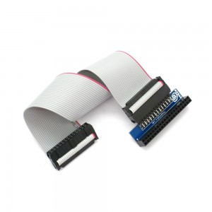
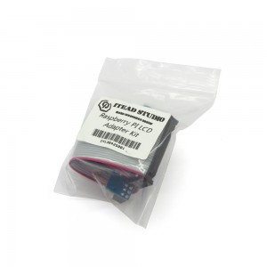
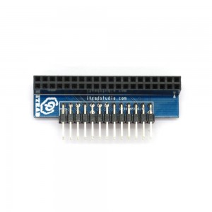
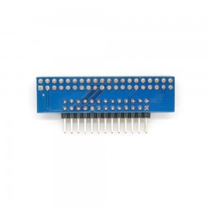
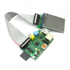
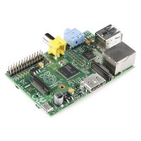
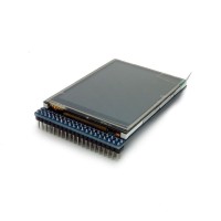
To facilitate the use of Raspberry Pi and screen module to work together, we specifically developed a simple adapter board and customized a batch of 26-pin (2X13) cable. Simply insert the screen module into the adapter board, then connect the board and Raspberry Pi plate with cable, thus the hardware connection is done, saving the trouble of corresponding connection of each pin.
This adapter kit is compatible with ITDB02-2.2, ITDB02-2.4E and ITDB02-2.8. NOT compatible with ITDB02-3.2S , ITDB02-3.2WD.
Pin Mapping
| Pin of ITDB02 LCD | Pins of Raspberry | Raspberry Pi Pin N.O. | Name |
| DB8 | D0 | 11 | GPIO0 |
| DB9 | D1 | 12 | GPIO1 |
| DB10 | D2 | 13 | GPIO2 |
| DB11 | D3 | 15 | GPIO3 |
| DB12 | D4 | 16 | GPIO4 |
| DB13 | D5 | 18 | GPIO5 |
| DB14 | D6 | 22 | GPIO6 |
| DB15 | D7 | 7 | GPIO7 |
| CS | D10 | 24 | CE0 |
| RS | D8 | 3 | SDA0 |
| WR | D9 | 5 | SCL0 |
| RST | D11 | 26 | CE1 |
| T_CLK | D12 | 19 | MOSI |
| T_CS | D13 | 21 | MISO |
| T_DIN | D14 | 23 | SCLK |
| T_DOUT | D15 | 8 | TXD |
| T_IRQ | D16 | 10 | RXD |
| VCC | +5V | 2 | +5V |
| GND | GND | 6 | GND |


