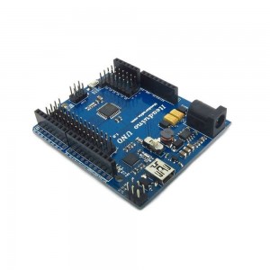
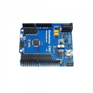
What's the different between Iteaduino UNO and Iteaduino? It does not use the FTDI USB-to-serial driver chip. Instead, it features the Atmega8U2 programmed as a USB-to-serial converter, and use the UNO bootloarder instead of Duemilanove bootloader. When you upload the program of Arduino IDE, choose the "Arduino UNO" under the "Tools"->"Board" memu , not the "Arduino Duemilanove or Nano w/ ATmega328".
The Iteaduino Uno is a microcontroller board based on the Arduino UNO. It has 14 digital input/output pins (of which 6 can be used as PWM outputs), 6 analog inputs, a 16 MHz crystal oscillator, a USB connection, a power jack, an ICSP header, and a reset button. It contains everything needed to support the microcontroller; simply connect it to a computer with a USB cable or power it with an AC-to-DC adapter or battery to get started.
Feature
- New external IO pin map
- Efficient DC-DC Power supply with wide range input.
- 3.3V/5V Operating Voltage selection
- All pins out for Sensor and Servo
- UART/IIC interface breakout
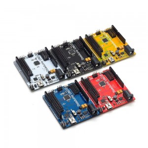
Note: Even though the Iteaduino UNO is available in 5 colors (Black, Blue, Red, White and Yellow), the color of the shipped board will depends on stock availability.
Hardware

Pin Mapping
|
Index |
Name of Arduino |
Alternate Function |
Pin of Atmega328 |
|
1 |
D0 |
UART DIN |
PD0 |
|
2 |
D1 |
UART DOUT |
PD1 |
|
3 |
D2 |
External Interrupt 0 |
PD2 |
|
4 |
D3 |
External Interrupt 1/PWM |
PD3 |
|
5 |
D4 |
- |
PD4 |
|
6 |
D5 |
PWM |
PD5 |
|
7 |
D6 |
PWM |
PD6 |
|
8 |
D7 |
- |
PD7 |
|
9 |
D8 |
- |
PB0 |
|
10 |
D9 |
PWM |
PB1 |
|
11 |
D10 |
SPI_NSS/PWM |
PB2 |
|
12 |
D11 |
SPI_MOSI/PWM |
PB3 |
|
13 |
D12 |
SPI_MISO |
PB4 |
|
14 |
D13 |
SPI_SCK |
PB5 |
|
15 |
A0 |
|
PC0 |
|
16 |
A1 |
|
PC1 |
|
17 |
A2 |
|
PC2 |
|
18 |
A3 |
|
PC3 |
|
19 |
A4 |
IIC_SDA |
PC4 |
|
20 |
A5 |
IIC_SCL |
PC5 |
Documents


